The Torsion Pendulum experiment for measuring the Rigidity Modulus is an important part of the first-year B.Sc. Physics practicals in the TANSCHE curriculum. This experiment allows students to dive into the idea of rigidity modulus, which is also called shear modulus. It’s a key characteristic of materials that shows how well they can withstand deformation when subjected to shear stress. By utilizing a torsion pendulum, students can find the rigidity modulus of a specific wire or material through careful measurements and calculations.
In this article, we will walk you through the experimental process, offering a clear, step-by-step guide on how to set up the torsion pendulum, perform the experiment, and compute the rigidity modulus. Grasping this experiment is vital for understanding the mechanical properties of materials, which is a fundamental part of both physics and material science.
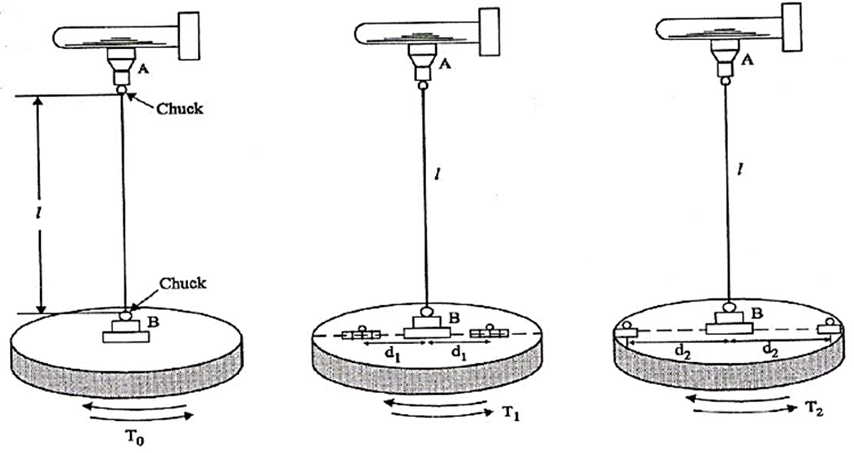
The wire's length between the fixed end and the chuck in the circular disc is adjusted to a length L. A reference line is marked on the disc. The disc is then gently twisted in a horizontal direction and released. It begins to perform torsional oscillations. The time taken for 10 oscillations is recorded. This process is repeated to find the average time for 10 oscillations. From this, the period T0 is calculated.
Two identical masses are positioned evenly on both sides of the suspension wire, each located a distance d1 (close to the wire) from the center (where d1 is the space between the center of the disc and the center of each mass). The period T1 is measured.
After that, the masses are kept at the distance d2 (far from the wire) from the center, and the period T2 is measured again. The time periods are measured for various lengths. The radius (a) of the wire is measured with a screw gauge.
d1 = _____ cm d2 = _____ cm


0 Comments
It's all about friendly conversation here : )
I'd love to hear your thoughts!
Be sure to check back again because I do make every effort to reply to your comments here.
Please do not post your website link here.