
In the first year of the B.Sc. Physics program under the TANSCHE syllabus, students get to explore a variety of essential experiments that enhance their understanding of basic physical concepts. One important experiment involves measuring the Rigidity Modulus through Static Torsion. The rigidity modulus, also known as the shear modulus, indicates how stiff a material is and how well it resists shear deformation. This experiment uses the static torsion method, helping students learn about the behaviour of materials when subjected to twisting forces.
In this blog, we will guide you through the detailed steps needed to carry out the experiment successfully, making sure you clearly understand how to measure the rigidity modulus using static torsion.
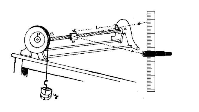
Rigidity modulus - Static torsion
(Mirror method)
Aim:
To determine rigidity modulus of the material of the rod using static torsion apparatus.
Apparatus required:
Static torsion apparatus, mirror, scale and telescope arrangement, weight hanger with weights etc
Formula:
Rigidity modulus,
Here,
G is the rigidity modulus of the material of the rod N/m2
L is the length of the rod from the fixed end to the mirror m
a is the radius of the rod m
R is the radius of the wheel m
D is the distance between the scale and the mirror m
s is the shift in scale reading for a load m
Procedure:
A strip of plane mirror is attached to the rod at a distance L from the end that is fixed. A vertical scale and telescope are set up and focused on the mirror, so the reflected image of the scale can be seen through the telescope.
First, with an empty weight hanger w, the scale reading that lines up with the horizontal cross wire is recorded. Then, weights are added in increments of m kg, and the corresponding scale readings are noted. After that, the weights are gradually decreased in steps of m kg, and the readings are taken again.
The torque is then reversed by wrapping the tape around the wheel in the opposite direction. The readings are recorded once more. From all these readings, the change in scale reading (s) for a load of (m) kg is determined. From these measurements (m/s) can be calculated.
This ratio can also be calculated by plotting a graph, with shift ‘s’ along the x-axis and the mass ‘m’ along the y-axis. This leads to a straight line. The slope of this line will give (m/s).

Radius of the R wheel is found by measuring its circumference with a thread and the radius of rod ‘a’ is measured using a screw gauge.
Tabular Column 1: To find the shift in the scale reading corresponding to the load
Tabular Column 2: To find the diameter of the rod using screw gauge
The procedure of using Screw gauge and its table can be found here.
From the average diameter (d) of the rod can be calculated. From this radius (a) can be found.


0 Comments
It's all about friendly conversation here : )
I'd love to hear your thoughts!
Be sure to check back again because I do make every effort to reply to your comments here.
Please do not post your website link here.