
Young's modulus - Cantilever
(Deflection method)
Aim:
To determine the Young's modulus of the material of the cantilever by measuring the depression at the loaded end using deflection method.
Apparatus required:
The cantilever, weight hanger and slotted weights, mirror, scale and telescope arrangement, screw gauge, vernier caliper etc.
Formula:
Young’s modulus,
Here,
E is the Young's modulus of the material of the bar N/m2
L is the length of the cantilever m
D is the distance between the mirror and the scale in the scale and telescope arrangement m
y is the depression corresponding to the load m
b is the breadth of the bar m
d is the thickness of the bar m
Procedure:
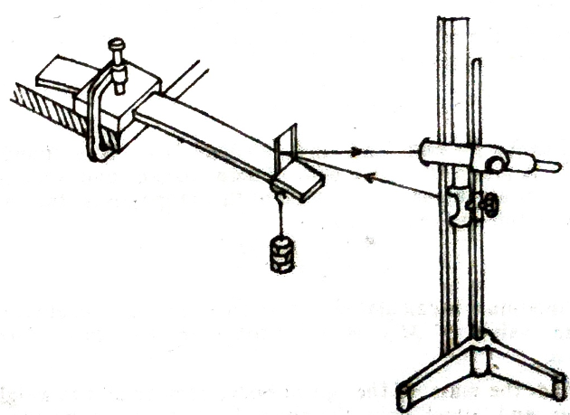
The bar is positioned along the edge of a table and firmly clamped, allowing a portion of it to extend past the table. A weight hanger is hung from a point close to the free end, where a mirror is vertically fixed. A scale and telescope arrangement are set up about one meter away from the mirror. The horizontal cross-wire in the telescope is aligned with a specific division on the scale, and the reading is recorded.
Initially, with only the weight hanger, the horizontal cross wire, and the reading from the vertical scale is recorded. Weights are then added in increments of 50 grams until the maximum load is reached, with readings taken each time. After that, the weights are removed in 50-gram increments, and the microscope readings are noted again.
From these readings, the average elevation of the midpoint of the bar due to the load ‘m’ applied is determined. From these measurements (m/y) can be calculated.
This ratio can also be calculated by plotting a graph, with elevation ‘y’ along the x-axis and the mass ‘m’ along the y-axis. This leads to a straight line. The slope of this line will give (m/y).

The breadth (b) and the thickness (d) of the bar are measured with the help of vernier caliper and screw gauge respectively. The experiment can be repeated with different values of L.
Tabular Column 1: To find the shift (s) corresponding to the load (m)
Load ‘m’ gm | Telescope scale readings | Mean cm | Shift in the scale reading for 100 gm ‘s’ cm | |||||
Loading cm | Unloading cm | |||||||
w | ||||||||
w+50 | ||||||||
w+100 | ||||||||
w+150 | ||||||||
w+200 | ||||||||
w+250 | ||||||||
Tabular Column 2: To find the breadth of the beam using Vernier calliper
Tabular Column 3: To find the thickness of the beam using screw gauge
Result:
Young's modulus of the material of the bar by the method of cantilever depression is found to be, E =______ N/m2


0 Comments
It's all about friendly conversation here : )
I'd love to hear your thoughts!
Be sure to check back again because I do make every effort to reply to your comments here.
Please do not post your website link here.