
Young's modulus Uniform bending
(Pin and Microscope method)
Aim:
To determine the Young's modulus of the material of a given bar by the method of uniform bending using a pin and microscope.
Apparatus required:
Uniform bar, wait hangers, weights, knife edges Vernier microscope, screw gauge, Vernier calliper etc
Formula:
Young’s modulus,
Here,
E is the Young's modulus of the material of the bar N/m2
m is the load added in the weight hanger kg
g is the acceleration due to gravity m/s2
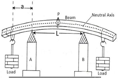
a is the distance between the point of suspension of the load and the nearer knife edge m
L is the length of the bar between the knife edges m
b is the breadth of the bar m
d is the thickness of the bar m
y is the elevation of the midpoint of the bar due to a load ‘m’ m
Procedure:
The given bar is placed symmetrically on two knife edges separated by ‘L’ length (say 60 cm). Two weight hangers are suspended at a distance ‘a’ (say 10 cm) from ends of the bar. A pin is fixed vertically at the centre of the bar using wax.
The tip of the pin is made to coincide with the crosswire in the microscope. The initial reading of the microscope on its vertical scale is noted.
Place two equal weights ‘m’ (50 gm) on the weight hanger. Adjust the microscope so that the inverted image of the pin tip is again aligned with the crosswire and record the microscope readings. Then, add weights in m (50 gm) increments until the maximum load is reached. Each time, take the microscope readings. The weights are then removed in equal steps and the microscope readings are recorded each time. The average value of load is obtained. From these readings, the average elevation of the midpoint of the bar due to the load ‘m’ applied is determined. From these measurements (m/y) can be calculated.
This ratio can also be calculated by plotting a graph, with elevation ‘y’ along the x-axis and the mass ‘m’ along the y-axis. This leads to a straight line. The slope of this line will give (m/y).

The breadth (b) and the thickness (d) of the bar are measured with the help of Vernier calliper and screw gauge respectively. The experiment can be repeated with different values of L.
Tabular Column 1: To find the elevation corresponding to load using Vernier microscope
Least count (LC) = 0.001 cm
MSR - Main scale reading;
VSC - Vernier scale coincidence;
VSC - Vernier scale reading (VSC = VSR x LC)
TR - Total reading (TR = MSR + VSR)
Load ‘m’ gm | Microscope readings | Mean cm | Elevation corresponding to 100 gm ‘y’ cm | |||||
Loading | Unloading | |||||||
MSR cm | VSR cm | TR cm | MSR cm | VSR cm | TR cm | |||
w | ||||||||
w+50 | ||||||||
w+100 | ||||||||
w+150 | ||||||||
w+200 | ||||||||
w+250 | ||||||||
Tabular Column 2: To find the breadth of the beam using Vernier calliper
The procedure of using Vernier caliper and its table can be found here.
Tabular Column 3: To find the thickness of the beam using screw gauge
The procedure of using Screw gauge and its table can be found here.
Result:
The Young’s modulus of the material of the given beam = _________ N/m2


0 Comments
It's all about friendly conversation here : )
I'd love to hear your thoughts!
Be sure to check back again because I do make every effort to reply to your comments here.
Please do not post your website link here.