
Young's modulus - Uniform bending
(Single optic lever method)
Aim:
To determine the Young's modulus of the material of the given beam subjecting it to uniform bending using a single optic lever.
Apparatus required:
The given beam, knife edges, weight hangers with weights, a single optic lever, scale and telescope arrangement, Vernier caliper, screw gauge, etc.
Formula:
Young’s modulus,
Here,
E is the Young's modulus of the material of the bar N/m2
m is the load kg
g is the acceleration due to gravity m/s2
a is the distance between the point of suspension of the load and the nearer knife-edge m
D is the distance between the single optic lever mirror and the scale in the telescope arrangement m
l is the perpendicular distance between front leg and the line joining the hind legs of the optic lever m
L is the distance between the two knife edges m
b is the breadth of the beam m
d is the thickness of the beam m
s is the shift in the scale reading m
Procedure:
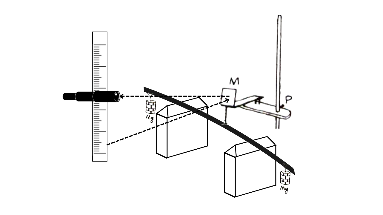
The rectangular beam is evenly supported on knife edges spaced a distance ‘L’ apart. Two weight hangers are suspended at a distance ‘a’ (say 10 cm) from ends of the bar. An optic lever's front leg is positioned at the center, while the back legs rest on a platform that matches the height of the knife edges.
A scale and telescope arrangement are set up about one meter away from the mirror of the optic lever. The horizontal cross-wire in the telescope is aligned with a specific division on the scale, and the reading is recorded.
Weights are then added to the two hangers in increments of ‘m’ (say, 50 gm), and the corresponding readings from the telescope are noted. This process is repeated while removing the weights as well, and all readings are organized into a table. From these measurements (m/s) can be calculated.

This ratio can also be calculated by plotting a graph, with shifts in the scale reading ‘s’ along the x-axis and the mass ‘m’ along the y-axis. This leads to a straight line. The slope of this line will give (m/s).
The beam's width ‘b’ and thickness ‘d’, using a Vernier caliper and a screw gauge, respectively. The distance ‘D’ from the mirror of the optic lever to the vertical scale on the telescope is also measured. An impression of the three legs of the optic lever is created on a paper, and the perpendicular distance ‘l’ between the front leg and the line connecting the hind legs is measured.
Tabular Column 1: To find the shift (s) corresponding to the load (m)
Load ‘m’ gm | Telescope scale readings | Mean cm | Shift in the scale reading for 100 gm ‘s’ cm | |||||
Loading cm | Unloading cm | |||||||
w | ||||||||
w+50 | ||||||||
w+100 | ||||||||
w+150 | ||||||||
w+200 | ||||||||
w+250 | ||||||||
Tabular Column 2: To find the breadth of the beam using Vernier calliper
Tabular Column 3: To find the thickness of the beam using screw gauge
Result:
The Young's Modulus of the material of the beam by the method of non uniform bending using single optic lever is found to be, E = _____ N/m2


0 Comments
It's all about friendly conversation here : )
I'd love to hear your thoughts!
Be sure to check back again because I do make every effort to reply to your comments here.
Please do not post your website link here.